Parametric Sizing Equations for a VTOL Tailsitter
Flying Wing with Adaptable Payload Mass
Abstract
This document presents a complete set of parametric sizing equations for a jet-powered tailless flying wing in a VTOL tailsitter configuration, whose payload mass is not yet fixed. All geometric quantities (wing area, span, chord, control surface dimensions, vertical fin area) and propulsive requirements (hover thrust, cruise thrust, engine count) are expressed as closed-form functions of gross mass, target speeds, and aerodynamic design parameters. Thrust sizing accounts for both the hover constraint (T/W > 1) and cruise drag, with the hover requirement dominating EDF count. Transition from vertical to wing-borne flight is characterized. The formulation enables rapid trade studies across 20–120 kg robot masses.
1 Sizing Calculator
Adjust the primary design inputs below. All outputs update in real time from the equations derived in §3. Speeds are specified in km/h; internal computations use SI units.
2 Design Parameter Definitions
2.1 Mass and weight
2.2 Speed
2.3 Aerodynamic coefficients
2.4 Wing geometry
2.5 Thrust and propulsion
2.6 VTOL tailsitter parameters
2.7 Control surfaces and fins
3 Equation Derivations
3.1 Wing area from the stall constraint
The most fundamental sizing equation. In steady level flight, lift equals weight. Lift is generated by a wing of area S moving through air of density ρ at speed V:
At the stall boundary, V = Vs and the lift coefficient reaches its maximum. Setting lift equal to weight and solving for wing area:
Rearranging yields the wing loading — how much weight each square meter carries:
For fixed stall speed and CL,max, wing loading is constant. Therefore wing area scales linearly with weight: double the mass, double the wing.
3.2 Cruise lift coefficient
After sizing for stall, verify that cruise is aerodynamically reasonable:
A healthy cruise CL for a fast compact wing is 0.2–0.4. Higher values indicate the wing is undersized for the target cruise speed.
3.3 Span and chord from aspect ratio
Aspect ratio relates span to area:
Since S ∝ m, span scales as √m. Doubling mass increases span by only √2 ≈ 1.414.
Tapered wing chords
With taper ratio λ = ct/cr, integrating the linear chord distribution to recover total area:
Mean aerodynamic chord
The MAC is the chord-weighted average used for CG placement (target: 18–22% aft of MAC leading edge):
3.4 Drag polar and thrust requirement
Drag is modeled with a parabolic polar: parasite drag (independent of lift) plus induced drag (penalty for finite-span lift generation):
The induced drag factor k derives from Prandtl's lifting-line theory, corrected by the Oswald factor for non-elliptical loading:
In level flight, thrust equals drag. Dividing by weight and substituting CL = (W/S)/q:
This is the master thrust equation. The first term (parasite) increases with speed; the second (induced) decreases. Their intersection defines minimum-drag speed.
Adding climb
Sustained climb at rate ROC requires extra thrust to gain potential energy:
Adding acceleration
Lift-to-drag ratio
For CD0 = 0.04, AR = 3, e = 0.8: (L/D)max ≈ 4.3. Modest but typical for this vehicle class.
3.5 EDF count
For a 10 kgf (~98 N) EDF with ηi = 0.90, each installed unit delivers ~88 N effective thrust.
3.6 Elevon sizing
Elevons serve as both elevator and ailerons on a tailless wing:
Total elevon area: typically 7–15% of wing area. Deflection range: ±12° to ±15°.
3.7 Vertical fin and rudder
Moment arm lv for tip fins ≈ 0.35b – 0.45b.
3.8 Reynolds number and airfoil selection
Tailless wings require reflex airfoils with Cm0 ≈ 0 to avoid trim drag. Choice depends on Reynolds number, not directly on mass. See §5 for the database.
3.9 VTOL tailsitter sizing
In a tailsitter configuration, the entire aircraft rotates nose-up for vertical takeoff and landing. All EDFs point upward, and thrust must exceed weight. The hover thrust requirement is:
where (T/W)hov ≥ 1.3 is required for adequate control margin in hover. This is the dominant sizing constraint for EDF count. For a 60 kg system with (T/W)hov = 1.4, hover thrust is 824 N — roughly 6× the cruise thrust requirement.
The number of EDFs is now set by hover, not cruise:
Transition from hover to wing-borne flight
The transition speed is the airspeed at which wing lift can fully support the aircraft weight, allowing the vehicle to pitch from vertical to horizontal. With a safety margin factor ftrans:
During transition at pitch angle θ from horizontal and forward speed V, the force balance requires:
The first equation says the vertical force (thrust component + wing lift) must support weight. The second says horizontal thrust must overcome drag and provide forward acceleration. At the start of transition (θ ≈ 90°, V ≈ 0), thrust alone carries the weight. As speed builds and the vehicle pitches forward, the wing progressively takes over. The transition is complete when θ = 0° and the wing carries full weight.
The critical design constraint is that enough thrust margin must exist throughout the transition corridor to simultaneously support weight and accelerate forward. The hover T/W ratio determines how much excess thrust is available for acceleration during the pitch-over. Higher (T/W)hov means faster, more controllable transitions but more EDFs.
Hover control authority
In hover, conventional aerodynamic surfaces (elevons, fins) are ineffective because there is no airflow over the wing. Yaw, pitch, and roll control must come from:
Differential thrust — varying thrust across spanwise-distributed EDFs provides roll and pitch moments. The moment arm equals the spanwise or chordwise distance between EDF pairs. Minimum practical configuration: 4 EDFs in a rectangular arrangement.
Thrust vectoring or control vanes — deflectable vanes in the EDF exhaust can provide yaw control and augment pitch/roll authority. This adds mechanical complexity but significantly improves hover controllability.
The moment authority in hover scales with span × thrust differential. Larger spans (higher AR) provide more roll authority but also more inertia to overcome. This creates a design tension not present in forward-flight-only configurations.
4 Scaling Laws
For geometrically similar designs at fixed stall speed, cruise speed, CL,max, AR, CD0, and e:
| Quantity | Scales as | 2× mass → | Meaning |
|---|---|---|---|
| S | ∝ m | 2.00× | Direct proportionality |
| Tcruise | ∝ m | 2.00× | Direct proportionality |
| Thover | ∝ m | 2.00× | Direct proportionality (dominates) |
| b | ∝ √m | 1.41× | Square root |
| c | ∝ √m | 1.41× | Square root |
| Se, Sv | ∝ m | 2.00× | Proportional to S |
| W/S | const | 1.00× | Fixed by Vs, CL,max |
| T/W | const | 1.00× | Fixed by aero + speed |
5 Reflex Airfoil Database
Tailless wings need airfoils with near-zero pitching moment to avoid trim drag from constant elevon deflection. A reflex trailing edge cancels the nose-down moment of conventional camber. Selection depends on Reynolds number.
| Airfoil | t/c | Cm0 | Cl,max | Re range | Notes |
|---|---|---|---|---|---|
| MH 78 | 8.5% | +.002 | 0.90 | 80k–300k | Small UAV scale |
| MH 61 | 9.7% | +.005 | 1.05 | 100k–400k | Classic low-Re reflex |
| MH 45 | 9.0% | +.003 | 1.00 | 200k–800k | Very low moment |
| S5010 | 10% | .000 | 1.00 | 200k–1M | Zero Cm0 baseline |
| EH 2.0/10 | 10% | +.005 | 1.10 | 300k–1.2M | Wide Re range |
| Eppler 325 | 11.2% | +.010 | 1.15 | 300k–1.5M | Forgiving stall |
| HS 3.0/9.0 B | 9.0% | +.002 | 0.95 | 500k–2M | Horten/Schumann gold standard |
| NACA 23112m | 12% | −.010 | 1.30 | 500k–3M | Higher Cl but needs trim |
All coordinates from the UIUC Airfoil Coordinates Database. Import into XFOIL / XFLR5 / AVL.
6 Design Considerations and Next Steps
The parametric sizing yields a first-pass geometry for simulation. Before hardware, the following analyses must close:
6.1 CG and trim closure
CG at 18–22% MAC ahead of the neutral point, maintained throughout flight as fuel burns. Aft CG → divergent instability; forward CG → excessive trim drag and inability to flare.
6.2 Thrust-line moment
If EDFs are offset from CG: MT = T · zoffset. This pitching moment consumes elevon authority and adds drag. Minimize zoffset; verify elevons don't saturate at max thrust.
6.3 Stability derivatives
Check Cmα < 0 (pitch), Cnβ > 0 (yaw), roll damping Clp, and Dutch roll coupling. Compute in AVL or XFLR5. Marginal Cnβ requires more fin area or a yaw damper.
6.4 Flutter margin
Bending-torsion coupling can extract energy from the airstream above a critical speed. Carbon skin torsional stiffness must keep flutter speed ≥ 1.4× VNE. GVT and FE modal analysis essential.
6.5 Structural bending/torsion
At +6g limit load, a 60 kg system sees ~3,500 N air load. Root bending: several kN·m. Main spar at ~25% chord with carbon caps + shear web. EDF mounts into primary structure, not skin panels.
6.6 Hover control and transition
In hover, aerodynamic surfaces are ineffective — control comes from differential thrust and optionally exhaust vanes. Minimum 4 EDFs in a rectangular layout for 3-axis control. The transition pitch-over from vertical to wing-borne flight is the highest-risk phase: thrust must simultaneously support weight and accelerate forward. Map the full θ-vs-V transition corridor in simulation before flight. Wind gusts during hover require fast thrust response — EDF spool-up time matters.
6.7 EDF layout for dual-mode operation
All EDFs must be positioned to provide both efficient forward thrust (aligned with flight direction) and adequate hover control moments. Spanwise distribution drives roll authority; chordwise distribution drives pitch authority. Symmetric placement is essential to avoid trim asymmetries. Consider cant angles (tilting EDFs slightly inward) to improve yaw control in hover at a small cosine loss in forward thrust.
6.8 Workflow
(1) Fix mass + speed. (2) Size wing from stall. (3) AR, sweep, taper. (4) Airfoil from Re. (5) CG at 20% MAC. (6) Size elevons + fins. (7) Hover thrust sets EDF count. (8) Verify cruise drag ≪ available thrust. (9) XFLR5/AVL for forward flight. (10) 6-DOF hover + transition simulation. (11) 1:3 scale RC tailsitter prototype. (12) Full-scale only after RC validation of transition.
7 First Design — 75 kg VTOL Tailsitter
This section documents the first concrete configuration, sized for a 75 kg gross mass system.
7.1 Performance
| Gross mass m₀ | 75 kg |
| Weight W | 736 N |
| Stall speed Vs | 90 km/h (25.0 m/s) |
| Cruise speed Vc | 160 km/h (44.4 m/s) |
| Rate of climb | 2.0 m/s |
| Transition speed | 108 km/h (30.0 m/s) at 1.2× Vs |
| Cruise L/D | 5.6 |
| Cruise CL | 0.28 |
| Wing loading W/S | 345 N/m² |
7.2 Wing geometry
| Wing area S | 2.14 m² |
| Wingspan b | 2.53 m |
| Mean chord c̄ | 0.84 m |
| Root chord cr | 1.12 m |
| Tip chord ct | 0.56 m |
| MAC | 0.87 m |
| Aspect ratio AR | 3.0 |
| Taper ratio λ | 0.50 |
| LE sweep Λ | 27° |
| Washout | 2° (root to tip) |
| Airfoil | NACA 23112 modified (reflex), 12% t/c |
| Root thickness | 134 mm |
| Tip thickness | 67 mm |
| Re at MAC | 2.63M |
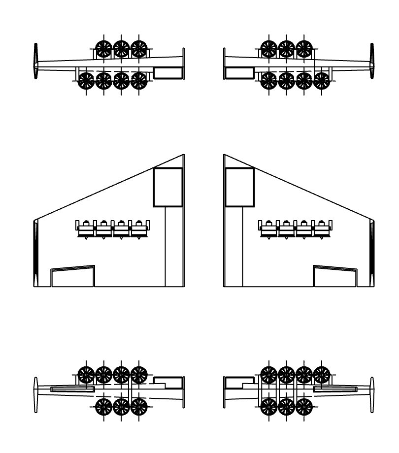
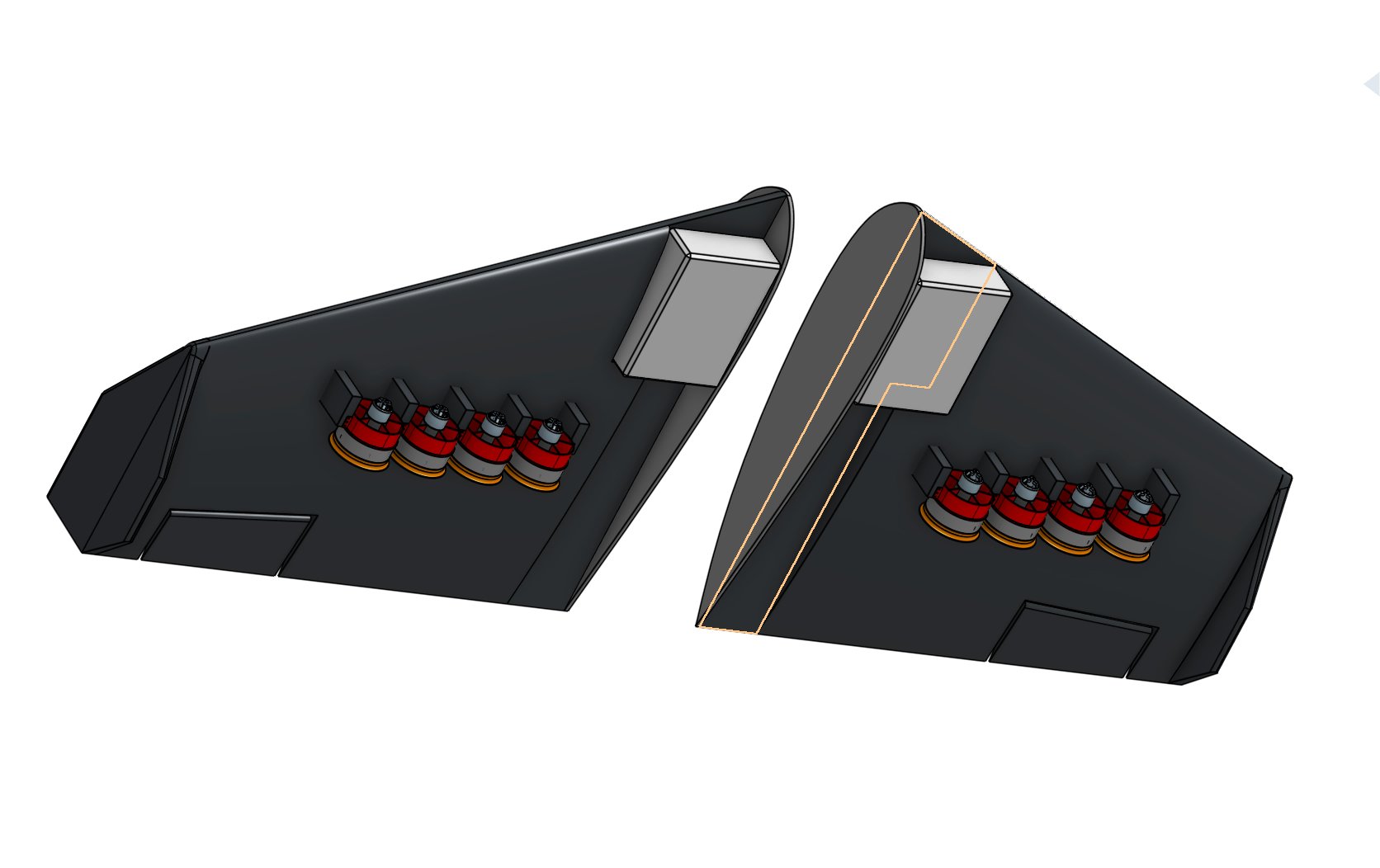
| Construction | Two-piece, split at centerline |
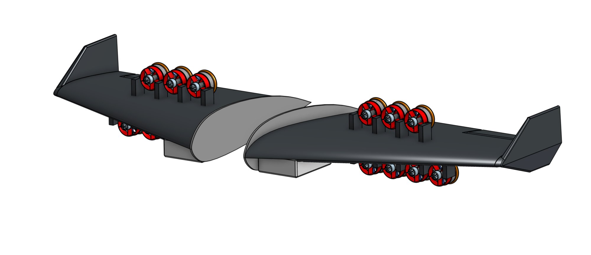
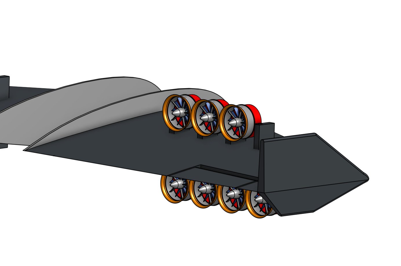
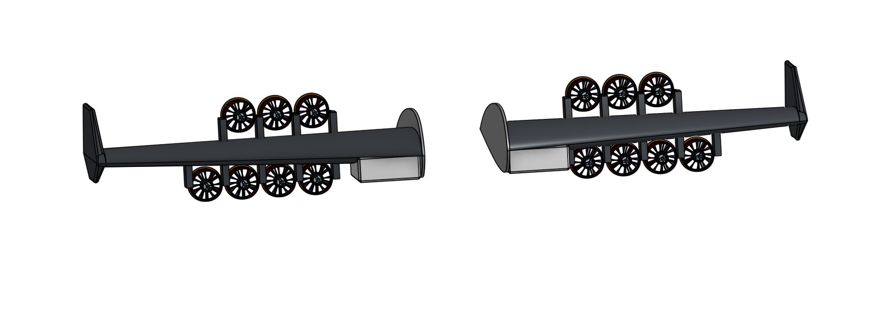
7.3 Propulsion — JP Hobby 120 mm EDF × 14
| EDF unit | JP Hobby 120 mm, 14S |
| Total count | 14 (7 per side) |
| Layout per side | 3 forward (row A) + 4 aft (row B), staggered |
| Per-EDF thrust | ~98 N (~10 kgf) |
| Per-EDF mass | ~900 g (with motor) |
| Total EDF mass | ~12.6 kg |
| ηi | 0.90 |
| Total installed thrust | 14 × 98 × 0.90 = 1,235 N (126 kgf) |
| Row separation | ~27 cm center-to-center |
| Cluster separation (L–R) | ~1.35 m center-to-center |
| Rotation pattern | 7 CW / 7 CCW, interleaved for yaw control |
| Cruise thrust | 164 N (16.7 kgf) — 2 EDFs sufficient |
| T/W cruise | 0.223 |
| Hover thrust | 1,104 N (112.5 kgf) at T/W = 1.50 |
| Hover/cruise ratio | 6.7× |
| Hover margin | 1,235 / 1,104 = 1.12 (12% above hover requirement) |
7.4 Energy — Tattu 30 Ah 14S HV
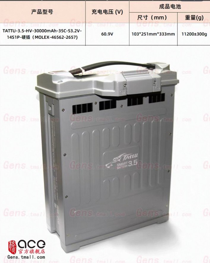
| Battery | Tattu 3.5-HV-30000mAh-35C-53.2V-14S1P |
| Pack count | 2 (parallel for current capacity) |
| Voltage | 53.2V nominal / 60.9V charge |
| Capacity | 30 Ah per pack, 60 Ah total |
| Max continuous | 1,050A per pack / 2,100A total |
| Dimensions | 103 × 251 × 333 mm per pack |
| Mass per pack | 11.2 kg |
| Total battery mass | 22.4 kg |
| Hover current draw | ~1,200A total (14 EDFs at ~85A each) |
| Cruise current draw | ~170A total (2–3 EDFs at cruise throttle) |
| Pure hover endurance | ~3 min (60 Ah / 1,200A) |
| Pure cruise endurance | ~21 min (60 Ah / 170A) |
| Typical mission | 30s hover → cruise → 30s hover = ~12–15 min total |
7.5 Mass budget
| Batteries (2×) | 22.4 kg (30%) |
| EDFs + motors (14×) | 12.6 kg (17%) |
| ESCs (14×) | ~2.8 kg (4%) |
| Wing structure | ~12 kg (16%) |
| Wiring + connectors | ~3 kg (4%) |
| Flight controller + sensors | ~0.5 kg (1%) |
| Remaining for payload | ~21.7 kg (29%) |
| Total | 75 kg |
7.6 Hover control architecture
All three hover axes are controlled through electronic thrust modulation — zero servos, zero mechanical actuators for attitude control.
| Roll | Differential thrust left vs right cluster. Arm = 1.35 m. Authority: ~139 N·m. Robust. |
| Pitch | Differential thrust row A vs row B. Arm = 27 cm. Authority: ~10 N·m nose-up, ~37 N·m nose-down. Supplemented by elevons as airspeed builds. |
| Yaw | Counter-rotating EDFs (7 CW / 7 CCW). Net reaction torque differential. No vanes. |
| V = 0 (hover) | Differential thrust + counter-rotation only |
| V = 0 → 45 km/h | Thrust primary, elevons beginning to contribute |
| V = 45 → 90 km/h | Blended control, elevons gaining authority |
| V > 90 km/h | Wing-borne — elevons and fins take over completely |
7.7 Control surfaces
| Total area | 0.188 m² (8.8% of wing area) |
| Span per side | 0.35 m (60–88% of semi-span) |
| Chord (inboard) | 0.17 m (22% of local chord) |
| Chord (outboard) | 0.14 m (22% of local chord) |
| Hinge line | 78% local chord |
| Deflection | ±12° to ±15° |
| Count | 2 × tip-mounted at 92% semi-span |
| Total area | 0.160 m² (0.080 m² each) |
| Fin height | 0.31 m |
| Fin root chord | 0.34 m |
| Fin tip chord | 0.17 m |
| Fin airfoil | NACA 0010 (symmetric) |
| Fin LE sweep | ~30° |
| Rudder | 35% chord, full span, ±15–20° |
7.8 CG and stability
| CG target | 20% MAC aft of MAC leading edge |
| CG from root LE | 0.46 m (41% of root chord) |
| Vv | 0.030 |